VCR (Voltage Controlled Rectifier)
Hi everyone!
Today, I want to show you a Voltage Controlled Rectifier, or VCR for short.
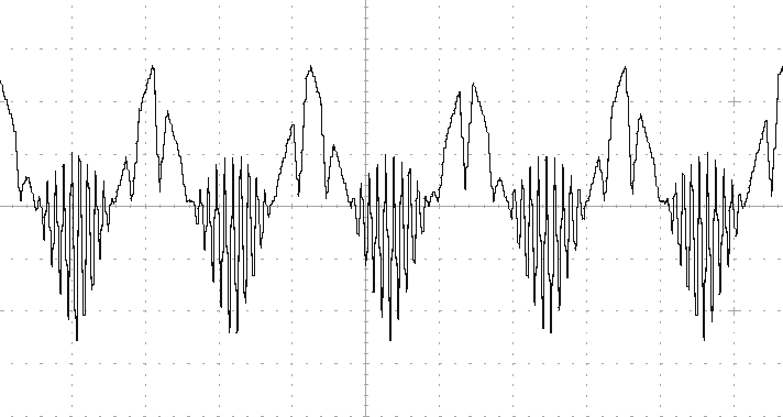
Why would you need a rectifier and voltage controlled one at that? Because it’s great for mixing and morphing control voltages, and it makes some crazy sounds when used with audio signals—think of it as a ring modulator but with three signals instead of two. You can get signals out of it looking like this:
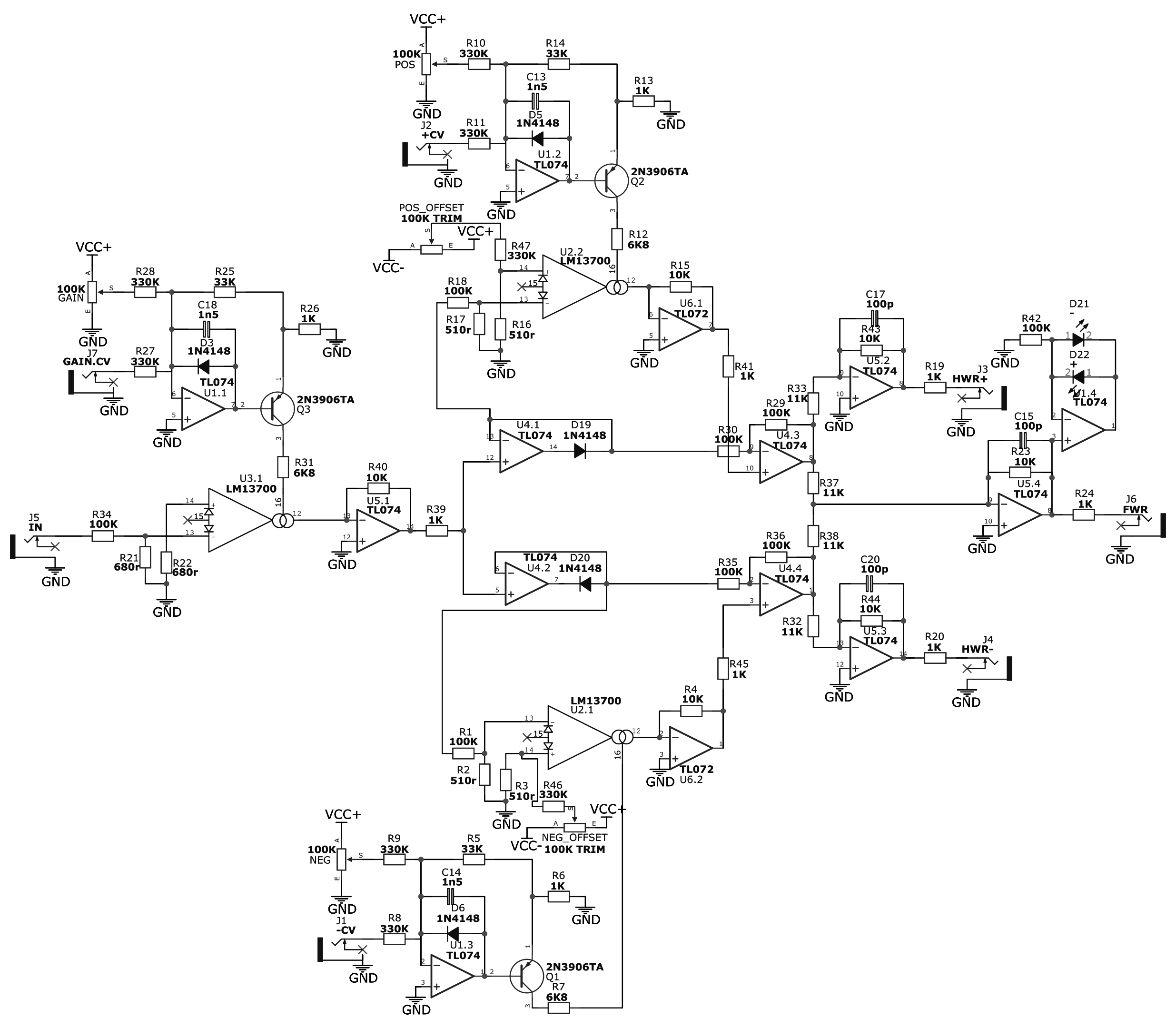
At first glance, this build might seem complicated, but I assure you, it is not. Most of the schematic consists of repeating parts, which can make it look big and complex.
I designed this circuit because I haven’t seen anyone do something like this, or maybe I didn’t look hard enough. Who knows? The idea is simple: add voltage control to a rectifier circuit. And what better way to do it than with OTAs?
First, OTA U3.1 serves as a VCA for the whole circuit, including the half-wave rectifiers. If that’s not what you want, you could move it to the input of the U5.4 op amp, affecting only the full-wave rectifier part. Or, you could remove it entirely if you want just the rectifier part without VCA.
At the outputs of every OTA, there is an op-amp current-to-voltage converter. It could be simplified by replacing it with a resistor to ground and an LM13700 built-in Darlington pair, but I wouldn’t advise that, as it distorts the signal too much. And yes, I tried it.
One last thing about OTAs is that they have a voltage offset. While in the VCA part, it doesn’t matter as much, in the rectifier part, it does. That’s why there are trimpots on each of the rectifier OTAs. You can remove them if you don’t mind that the waveforms will have a bit of an offset, but it will affect the overall waveform and how it reacts to control signals. This isn’t always a bad thing. It’s easy to try while building this—maybe you’ll like it that way.
Both U4.3 and U4.4 do the same thing, each for their own half of the waveform. The idea is simple: when the OTA passes the signal to the non-inverting input, the op-amp follows the signal on its output. When it’s turned down, the non-inverting input sees 0V, and the output tries to compensate for the signal present at the inverting input, outputting an inverse of the signal.
Next, the signal gets split to the half-wave rectifier outputs and a mixing circuit that combines both halves of the signal and sends them to the output. And that’s basically it. As I said, not complicated at all.
There are some parts that could be simplified or improved upon. For example, you could figure out what to do with the other half of the LM13700 IC used for the VCA, or you could remove the VCA entirely. You could also add an input buffer, which isn’t strictly necessary but wouldn’t hurt. I’m sure you can think of some ways to improve this circuit. If you have suggestions on how to improve it or find any mistakes, be sure to tell me at support@tremodular.com .