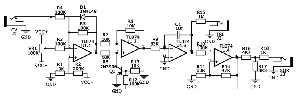
TL074 VCLFO
Hi everyone!
Today I want to show you this rather simple but useful DIY project. It is a VCLFO that can be built using only one TL074 IC.

In the configuration shown in the schematic it has a range of ~0.09Hz to 16Hz . You get two waveforms – triangle and square.
This is a voltage controlled, voltage driven oscillator. That means that it runs directly using supplied control voltage to oscillate.
U1.2 with help of Q1 and the signal from U1.4 switches between the control voltage and inverse of it that goes to the integrator.
Voltage to U1.2 is supplied from U1.1. U1.1 does three things – it combines the control signals, inverts them and with help of D1, R1 and R2 keeps its output from reaching 0v. Reference voltage at U1.1 non-inverting input should be greater than the voltage drop of D1 to keep U1.1 output always negative. If U1.1 output reaches 0v LFO stops oscillating. You can substitute R1 and R2 with a trimpot to dial in the precise voltage that you need. It will let you get closer to the 0v and thus make it oscillate slower on the low end.
Resistors R6, R7 and R8 should be matched to prevent triangle wave from skewing to one side.
Easiest way to change the range of this LFO is by changing C1 and R9.
Good luck with the build!